 Fig. 1
In the world of older Macintoshes clock batteries are failing. The result is a time-of-day clock that doesn't run and, worse, parameter RAM that doesn't keep settings when a machine is idled. Batteries are often soldered in and they have been made from elements now considered environmentally nasty such as mercury and lithium. The lithium cells were touted at the time as being so good that they could be soldered in and last for the life of the product. Sigh. Old Macs are still running and the cost of a replacement battery is more than the market value of the Mac.
The pictures below are kept small. You can click on them to show a more detailed picture that you can save if you want.
You will need a few tools. A pair of small wire cutters, a small soldering iron, some rosin-core solder, a pair of forceps or needle nosed pliers, a small file. A vise or other clamping tool is useful though a willing helper can provide the same services. A nice thing to have around is a voltmeter with which you can check cells for polarity and entire batteries for life. I saw some at Harbor Freight for less than $4. Though it's not really necessary it makes for a good feeling when you check your work for the right voltage on the pins before you plug it into a computer. Multimeter points to something like it today but things change rapidly.
Fig. 1
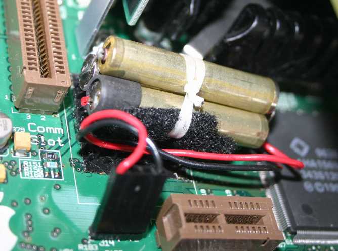
Here is a photograph of a replacement battery for a Mac 6400 that I made from half of a "standard" 9 volt battery and installed. I was working on a stack of 5260 and 5500 machines taken out of a local school. The destination was the homes of less fortunate students. The 4.5 volt alkaline batteries were just too expensive while my time (retired) was cheap even though it won't come out of my taxes.
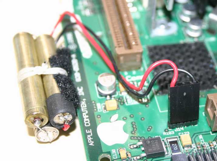 Fig. 2
The battery is held in place with a strip of rough cloth which was cemented to the original battery and engaged into a receiving patch of hooks permanently built into the printed circuit board. Here it is removed but not disconnected. Notice how the cloth strip is tied to the cells of the new battery. I just pulled it off the old battery as I cut off its wires and connector for re-use.
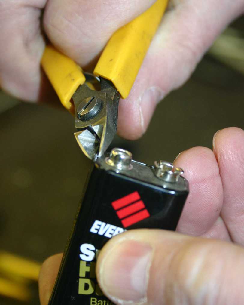 Fig. 3
Now that you know the result take a look at the process. I didn't make pictures during an actual build and these are fakes taken just for this report. You'll see in a minute that not everything came out just right. Here you see a 9 volt battery which I removed from a voltmeter that has been using it for years. It was nearly dead but I figured it was good enough for show and tell. A small pair of wire cutters will act as a can opener to peel off the light metal covering of the battery.
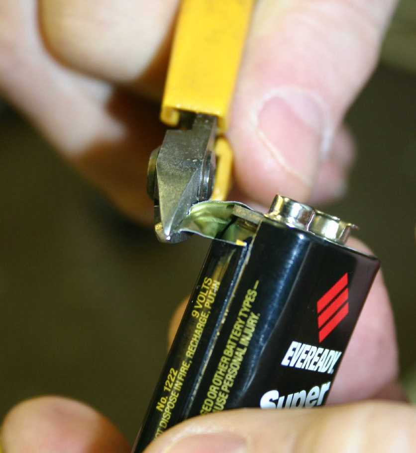 Fig. 4
Here I have cut into the rim and started pulling off the cover. It's much thinner than a tin can and it tears easily but it's quite easy to cut a finger on the sharp edges. A little care goes a long way.
 Fig. 5
Peeling off a little more. I used the cutter like a spool to roll the metal up onto it. I like to save the two snaps because they make replacement parts for worn out connectors in other equipment powered by 9 volt batteries.
 Fig. 6
When I got far enough down to expose the individual cells of the battery I expect them to come out easily as six little cylinders like the one shown in the pictures above. Oops. The old battery was made from a different kind of cell which was once the norm. Instead of six cylinders there are six rounded rectangles. They might be usable but soldering wires to their faces will be quite difficult. The moral is: Make sure your source of new batteries uses cylinders. Don't bother asking the clerk at the Radio Shack or grocery store. From here on let's assume that the battery provided six cylinders. Note that the cells are 1.5 volt carbon-zinc devices much like series AAAA. . cells you might buy. They use a KOH, potassium hydroxide, electrolyte and are properly called alkaline cells. If you poke a hole in one it will leak and the stuff that comes out is corrosive and might bother your skin. If you do that wash your hands. Please don't lick it off. The alkali is much like drain cleaner. Warnings are appropriate but it really won't hurt you.
 Fig. 7
So we now have cylinders. They have insulating varnish on the connections that needs to come off to prepare for soldering. Here I am using a small file to clean down to bare metal. Take note that the small tit shown is the negative end of the cell. That is different from the "standard" for common single cells used in flashlights. There is a story about that but not here.
 Fig. 8
After cleaning the tip I use a small soldering iron to "tin" the metal. Tinning is a process of getting the solder to wet the metal. Rosin in the core of the solder (Don't even think about acid core plumber's solder) keeps the air away and a little bit of scratching with the iron will allow the liquid solder to make a small puddle on the metallic tip of the cell.
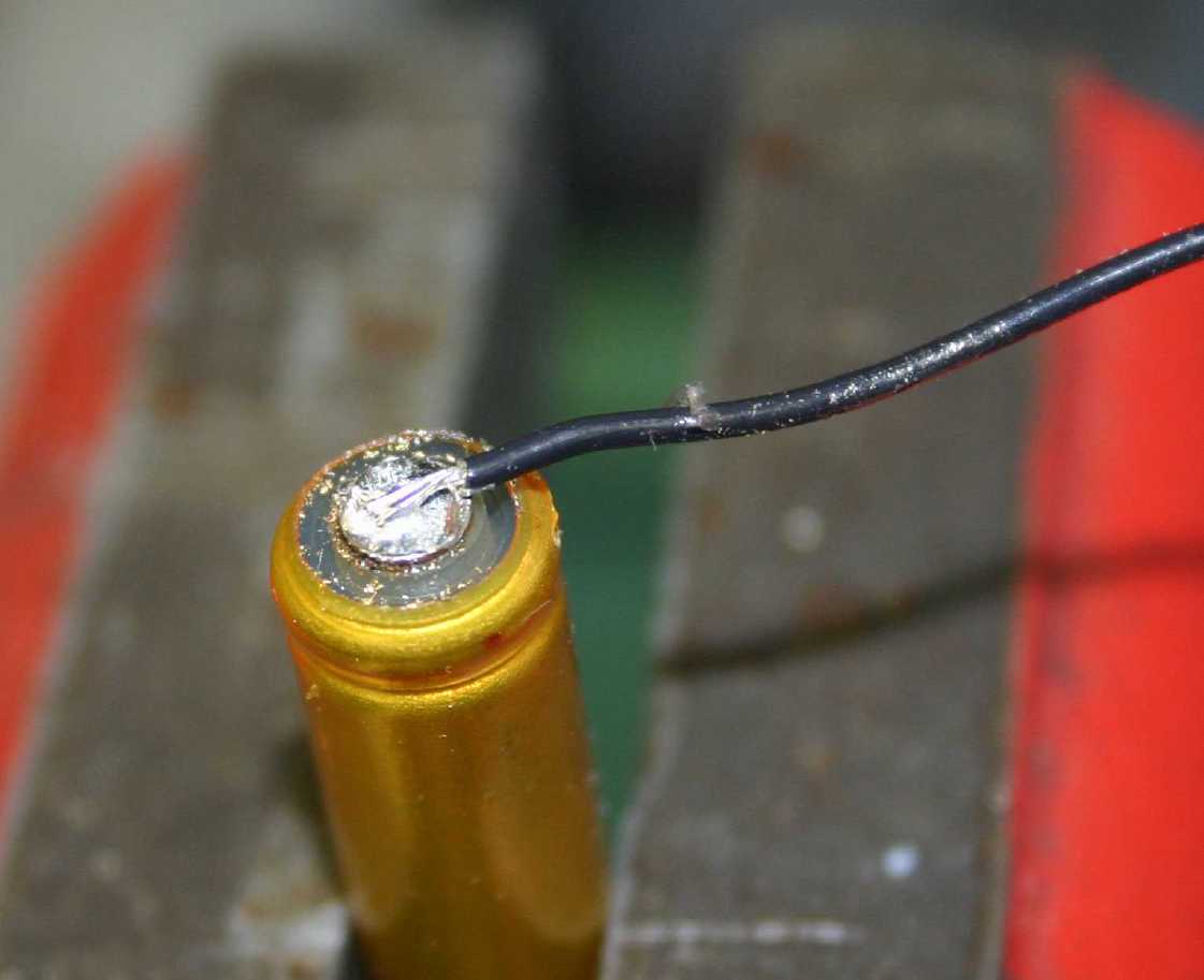 Fig. 9
After the solder puddle is prepared put away the solder and use just the iron and the wire to reflow the solder and attach the wire. It helps to tin the wire first. Note the black wire on the small end of the cell. Black and negative go together in electronics even though they don't in your household wiring in the walls.
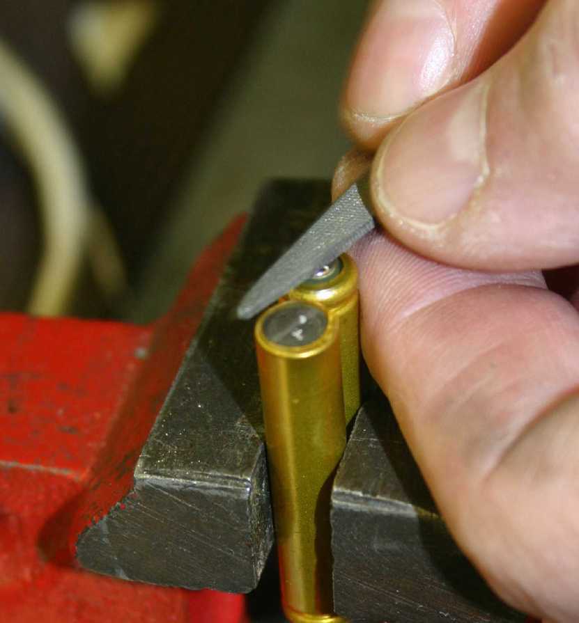 Fig. 10
With one wire connected pick up another cell and clamp them down together with the new wire down and out of sight and the positive end of its cell up. The new cell has the negative end up. Use the file to clean up the metal as before.
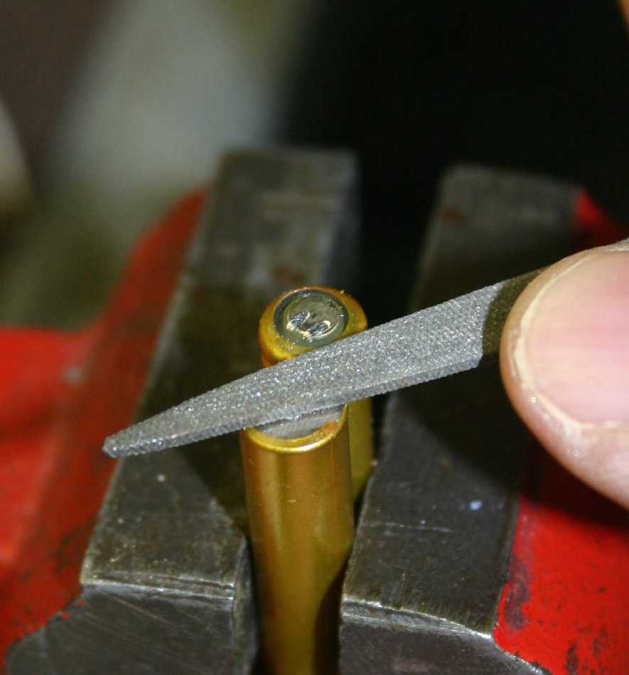 Fig. 11
Clean the positive end of cell number 1. This is a bit trickier because you will be engaging the insulation on the cell. Be careful not to get too much of it.
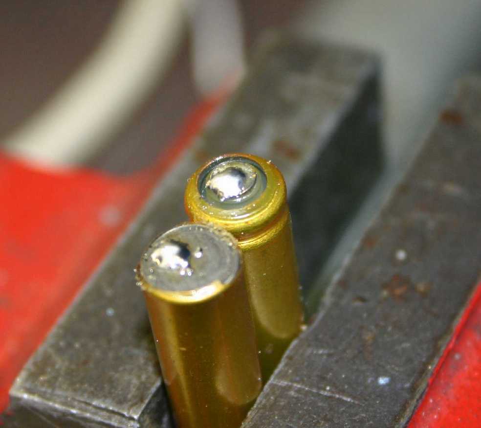 Fig. 12
Here is what the pair look like after you use the iron and solder to tin the ends of the cells.
 Fig. 13
Now a short piece of uninsulated wire is attached with the iron. The only reason for the long nosed pliers is to keep from burning your fingers. For wire I use the ends of axial resistors that are always around an electronics shop but surely you can find some wire around. Even a paperclip would work but something made from copper is better. If it's not tinned already use the iron to wet it with solder.
 Fig. 14
Attachng the other end is easy but you need to be careful not to get it hotter than necessary. It's embarrassing if the heat causes the first side to pop off.
 Fig. 15
When you're done it should look like this. You may worry about insulation but don't. We're talking about 3 volts here and I'll bet you can't even feel it. On your toungue you might and the experience is worth it.
 Fig. 16
The third cell is a bit trickier because the things want to slide all over each other. I like to use wax impregnated electronic lacing cord to tie things together with Boy Scout knots but here I'm using a piece of sticky tape. It's easier that way but sticky stuff is a pain to work with a few years later. You now need to make another jumper on the end of the group that has the black wire. It's the same process and there are no pictures. Be sure you connect a positive end to a negative end leaving a final connection on a positive - flat - end. If you look carefully you will see some red stuff on my finger. I did tell you to be careful with that thin metal covering the battery didn't I?
 Fig. 17
Here were are set up to add the positive wire. The file has been used to clean the metal.
 Fig. 18
Tinning the last end.
 Fig. 19
Ready for the red wire.
 Fig. 20
Attaching the red wire. Nothing new here.
 Fig. 21
And here is the nearly completed batery compared to the old. Note that I have cut those red and black wires, and their connector, from the old battery. Your installation may be different and you will have to take care of things like attaching the sticky cloth or providing for installation into the computer based on what you have around. On an old Mac II which used two lithium cells of 3.1 volts each I used four cells with three wires, one in the center, and soldered my three wires onto the motherboard. I put the cells into a plasitic zip-lock bag and just let it float around inside the computer. In another case I soldered wires to brass washers which I spaced out with a piece of rubber tubing to simulate the size and shape of a snapped-in lithium cell.
Douglas P. McNutt
The MacNauchtan Laboratory
7255 Suntide Place
Colorado Springs, CO 80919-1060
voice 719 593 8192
dmcnutt@macnauchtan.com
http://www.macnauchtan.com/
ftp://ftp.macnauchtan.com/